D3v4 工作坊 - React + D3 繪製 svg 動態路線地圖
前言
以前在做一些跟地圖有關的應用時,第一個出現在腦海的不外乎是 Google Map 和 OpenStreetMap,然後搭配 Leaflet 與 Mapbox 等工具來對 map tile 做各種加工渲染,然而到了工作上需要時就會發現這些工具在不付費、遵守授權的狀況下,就出現了各種限制,像是需要自己架設 tile server 來轉換 OpenStreetMap 的圖資,或是 request 的次數限制等等。
想了想發現最好的替代方案就是直接用 svg 來繪製,雖然沒有辦法像 Google Map 那般詳細,但在某些應用上來說就非常足夠,效果也很好,因此今天就來紀錄一下該如何使用 D3.js 與 svg 來繪製出有動態路線功能的地圖,讓大家可以做出類似中央氣象局的颱風路線預覽圖的作品!
先看一下成品:(P.S. 最近發現 codesandbox 這個服務,比起在 jsbin 或是 jsfiddle 上寫 React 來說好用一些,缺點是 mobile 體驗較差)
地圖資料搜集
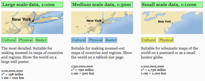
要自己畫地圖,當然就必須自己準備好圖資,看你想要台灣地圖或是世界地圖,基本上在網路上都能找得到,但是在使用網路資料的時候都需要小心授權條款,以世界地圖為例,目前我看到最能自由運用的就是 Natural Earth 的資料了,基本上有分三種比例的圖資,1:10m、1:50m 與 1:100m:

從 Natural Earth 載下來的會是 Vector data,無法直接使用在 D3.js 上,好在 D3.js 的作者 Mike Bostock 製作的另一套工具 topojson 中已經有 parse 過後的 TopoJSON 檔案,可以直接透過 https://unpkg.com/world-atlas@1/world/110m.json 取得,50m 的也有,就換一下後面的檔名即可。
如果你想要其他 Natural Earth 上的資料,其實也可以修改 world-atlas 裡面的 script 來自己轉換成 TopoJSON,可以參考我 fork 過來修改的這份檔案 prepublish-populor-place.sh,用來 parse Natural Earth 上的 popular_place data。
繪製基本的 svg 地圖
已經有了資料來源,就可以開始動手將地圖繪製出來了!
首先,React component 的起手式先準備好:
1 | import React, { Component } from 'react'; |
我在 componentDidMount 的時候去抓取地圖資料,接著才 setState(),但實際上你的專案可以先把資料存起來,這樣一來在 render 的地方就可以直接先 render 出 svg 地圖,這對於採用 Server-side rendering 的專案來說會方便很多,因為如果全部用 D3.js 的話,會需要先 select 到 DOM object 才能進行繪製,會麻煩一些。
利用 svg path 繪製世界地圖
在 svg 底下 append 一個 group,然後 iterate state 中的世界地圖資料,加上每個區塊的 svg path:
1 | <g className="countries"> |
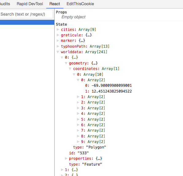
這邊先看一下我們 state 中的 worlddata 到底是什麼東西:

這是一個 TopoJSON 的格式,TopoJSON 簡單來說可以當作效能更好的 GeoJSON,詳細介紹可以看 這裡。Array 裡面的每一個 object 都是 type 為 Feature 的物件,其中的 geometry 包含了實際的地理資訊,可能是一個 Polygon,以及此 Polygon 每個點的座標。
接著我們需要使用 d3-geo 中的 geoPath,其中有 projection() method 能讓我們把剛剛的座標投影(project)到我們繪製的地圖上。
投影在地圖的繪製中扮演著極為重要的角色,透過投影,我們才能將真實世界的經緯度映射到我們網頁上小小的 svg 中。
d3-geo 中的 geoPath.projection() 會回傳一個 function,讓你傳地理資訊進去,接著回傳映射過後的 svg path,基本上就是一連串的 svg mini language,就是下列程式碼中的 d 的內容:
1 | <path d="M 10 25 |
M 代表將 筆 移動到 (10, 25),接著 L 畫一條線到 (10, 75),以此類推。詳細介紹可看 這裡。
當然,你必須傳入一個參數,告訴 geoPath.projection() 你想要映射的範圍為何,也就是 world_map_path.js 中 #L6 所傳入的 this.projection():
1 | projection() { |
也是回傳一個 Function,利用到 d3-geo 的 geoMercator,可以定義好你要映射的 scale 是多大,中心位置在哪。
最後為了讓每個國家的區塊有明顯區分,我們在 fill 的地方,隨機給他不同的顏色,fill={ rgba(219, 163, 43,${ 1 / this.state.worlddata.length * i}) }
到這個步驟你已經可以畫出下面這樣的地圖了:
繪製動態路線 - 資料準備
接著進行重頭戲,我們要在地圖上繪製出動態的路徑圖。
第一個步驟也是先準備好資料,以文章開頭的成品來說,是我修改某年的颱風路徑資料而成的,如果想要串接目前的颱風路徑圖,可以到 氣象資料開放平臺 申請會員,就可以拿到 API Key 去索取資料,格式會是 xml。
API 範例:http://opendata.cwb.gov.tw/opendataapi?dataid=W-C0034-004&authorizationkey={你的 API key}
其中 W-C0034-004 是颱風路徑圖資料的 data id。
資料中會有三個個主要部分,分別是過去的路徑資料 (past)、現在的位置 (curr) 與 未來預測的位置 (fcst),簡單的 parser 可以參考我的 gist
出來的結果格式如下,主要包含經緯度座標與颱風半徑:
1 | { |
繪製動態路線 - 路徑繪製
資料產生後,記得先放到 state 當中:
1 | const { pastData, currData, fcstData } = require('./parsedWeatherData.json'); |
順便加上一個 marker,用來代表颱風本體,以路徑圖的第一個位置為其座標起始點。
接著我們另外寫一個 renderLine() function 來處理路徑繪製的部分,因為待會還會需要加上動畫效果,會複雜一些:
1 | renderLine() { |
繪製路線的 renderLine() 可以拆成三部分來說明:
座標映射:
由於我們自己 parse 的路徑資料並非 TopoJSON,而且還區分成不同時間的資料,所以我們先個別將路徑映射好座標點,再串接到一個 Array 中,方便後續繪製。
我們先前提到的projection()非常好用,只要傳入一個含有 x, y 經緯度的物件,就能幫我們在設定的 scale 中映射出對應位置:this.projection()(path.coordinates),會回還一個 Array,分別為經度和緯度。線段繪製函數:
在 D3.js 中,attribute 可以傳入 function,這邊我們利用d3-shape中的line( code 裡面的 d3Line 是我 import 後的變數名稱)來幫忙將映射後的座標 x, y 轉換成 svg path 的 d value。
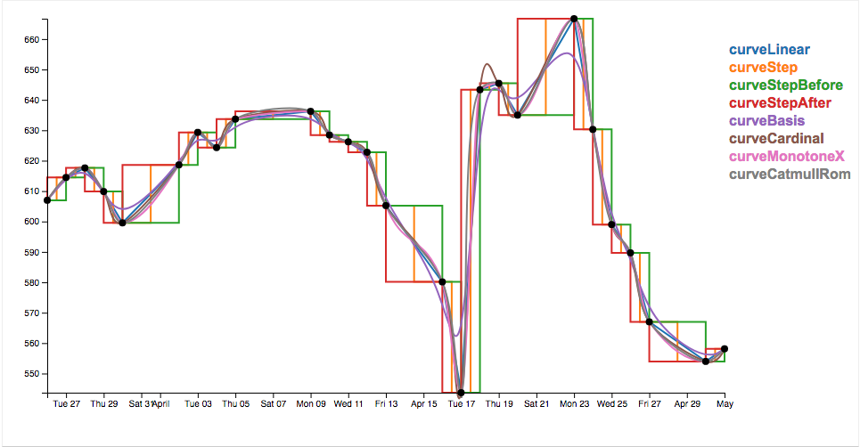
其中curve是d3-shape.line的補間函數,簡單來說就是決定線段中,每個 點 與 點 之間該怎麼 連接,看過這個對照應該會比較能了解:
v4 curve interpolation comparison

增加 svg 元素:
這就是最基本的步驟囉,d3-select出 svg 後,再 append 上我們要的 line path 與 marker,有寫過 D3.js 的勢必不陌生。
在 componentDidMount() 的地方加上 renderLine() 函數,就可以看到如下結果:
繪製動態路線 - 加上動態路徑效果
接著我們要讓這個路徑 活起來!
要讓 svg 線段有動畫般的效果其實很簡單,利用 svg 的 stroke-dasharray 這個屬性即可,詳細的實作原理可以看 css-tricks 上的這篇文章 How SVG Line Animation Works,解釋的非常清楚,只是裡面說的做法是透過 CSS 的 animation,跟我們這邊有些微差異,但是原理是相同的。
stroke-dasharray 的參數是 ( dash 的長度, gap 的長度 )),我們只要固定 gap 的長度為線段長,然後讓 dash 的長度從零慢慢轉換成線段長即可達到動畫效果!
所以我們加上一個 transition 函數:
1 | transition(linePath) { |
linePath 是 d3-select 到的路徑 path 元件。透過 transition() 與 attrTween() 來動態調整 stroke-dasharray 的值,並且在最後監聽一個 end 事件,也就是當每次動畫結束以後,我們隔個 1.5 秒再重新呼叫一次 transition(),進行 loop。
[Note]
這邊要注意的是,linePath 雖然是透過 d3-select 取得的元件,要呼叫他的 transition() 函式的話,會需要額外加入 d3-transition 的 lib 才行,他會將 transition bind 到元件中:import { transition as d3Transition } from 'd3-transition';
attrTween 會將 transition 過程中的時間當作參數丟進去給它的 value,而該 value 扮演著處理 補間動畫 的角色,是一個 input 為時間的補間函式,我們這邊執行一個translateFn(),用來處理我們補間動畫過程中需要做的事情,以及定義補間動畫函式的內容:
1 | translateFn(linePath) { |
如同先前提到的,我們要改變 stroke-dasharray 的區間,也就是要讓第一個參數,dash 的長度遞增為線段長,線段長度可以從 linePath.node().getTotalLength() 取得,透過 d3-interpolate 幫助我們產生一個補間函式 interpolate(t),補完 0, 線段長 -> 線段長, 線段長 這段參數的變化,並且回傳出去給 attrTween。
d3 的文件都顯得蠻詳細的,d3-interpolate 這邊有說明不同的 input type 會採用不同的補間函式來處理,例如字串、時間、數字等等。
加上了這個 tranlsateFn 後,線段就活起來了!
在剛剛的 translateFn 中我們其實還做了一件事情,就是讓 Marker 跟著線段移動,透過 const p = linePath.node().getPointAtLength(t * l); 取得線段在該時間的 point 位置,並 transform 過去。
但這樣還不夠,既然是想要有颱風路徑的效果,怎麼可以缺少了暴風半徑的資訊呢?
記得我們原本 parse 出來的資料中有個 radius 的值嗎?我們可以在 translateFn 中抓出目前資料的半徑值,然後放到 marker 的 r attribute 中:
1 | self.state.typhoonPath.forEach((path) => { |
但這邊還有個小問題,資料中,半徑的單位是 km,我要怎麼讓它轉換成 svg 中的距離呢?!我們之前的投影函式 projection() 只能接受座標參數,沒辦法直接轉換距離啊!
別慌張,那我們就先計算出中心點到這段半徑後的座標,在轉換成地圖上的點,接著利用國高中數學計算出距離即可!
1 | distanceCalculate(pixelLocSource, [longitude, latitude], distance){ |
取巧的點是,利用已知的經緯度距離來做運算:
Latitude: 1 deg = 110.574 km
Longitude: 1 deg = 111.320*cos(latitude) km // 該緯度上每一個經度的距離算法
pixelLocSource 是映射過後的中心點位置,[longitude, latitude] 則是中心點的原始經緯度,而 distance 就是我們要算的暴風半徑。
由於我們並不需要算出真正半徑內每個點的經緯度,所以這邊我只抓該緯度上的精度來做投影計算,找出該半徑後的精度,再套用普通的兩點距離公式。
(其實這是我想出來比較暴力的解法啦,歡迎知道有更簡單更好的方式映射距離的朋友告知我!非常感謝)
最後的成果(將 scale 調大比較看得出來半徑變化):
結論:
要讓路徑在地圖上動起來並不困難,而且透過 D3.js 的補間函式也能讓你在補間過程中偷做許多手腳,像是我最一開始的範例中還有多判斷資料的時間,針對不同時間留下颱風半徑範圍圖等等。
本篇的重點在於如何單純透過 D3.js v4 與 svg 的操作來製作出地圖上的動態線段,其他像是基本的經緯度線段 (graticule) 礙於篇幅關係就不細談,相信大家可以從我最一開始的範例中看出是如何製作的。希望本文能對想用 svg 繪製動態路線圖的讀者有所幫助,若文中有任何錯誤也歡迎指正!
資料來源
- Natural Earth
- topojson
- How SVG Line Animation Works
- SVG Paths and D3.js
- TWEENING CUSTOM SHAPES AND PATHS IN D3.JS
- SVG D3.js - 繪製線段
- D3.js Path Data Generator Line Example
- v4 curve interpolation comparison
關於作者:
@arvinh 前端攻城獅,熱愛數據分析和資訊視覺化

留言討論